
Making the input and output in phase is not a simple option without doing a lot of mods around the opamps, so we have to find something else.
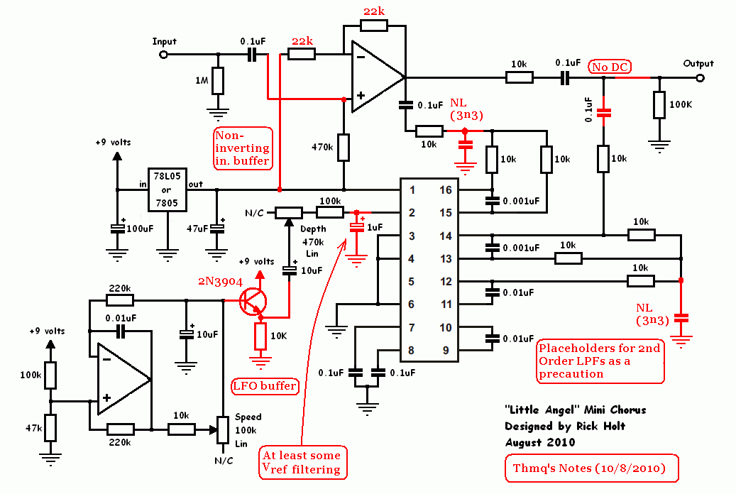
PT2399 SIMPLE DELAY SCHEMATIC MOD
The third thing is: creating endless feedback.Īlthough it is possible to achieve endless feedback using an external mixer with attenuverter function (remember in and output are intentionally out of phase for karaoke use), doing this with a simple mod is so much nicer! With a simple trick, we can keep the installed 50k pot, and change it into a 100k pot without desoldering or damaging it!) Now we have created a tamed beast till 12 o’clock, and a wild beast for the second half of the range! Interestingly, the time pot (like all pots) is a stereo pot, where only 1 side is used. So, to expand the delay in both directions, the 10k resistor may be changed by a 2k2 resistor (practically, it’s not needed to desolder the installer 10k resistor, just mount a 2k7 resistor in parallel!), and the potmeter may be changed by a higher value.


Once the board is on, making this resistor 0 is perfectly OK).

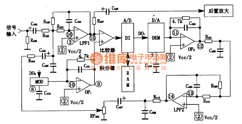
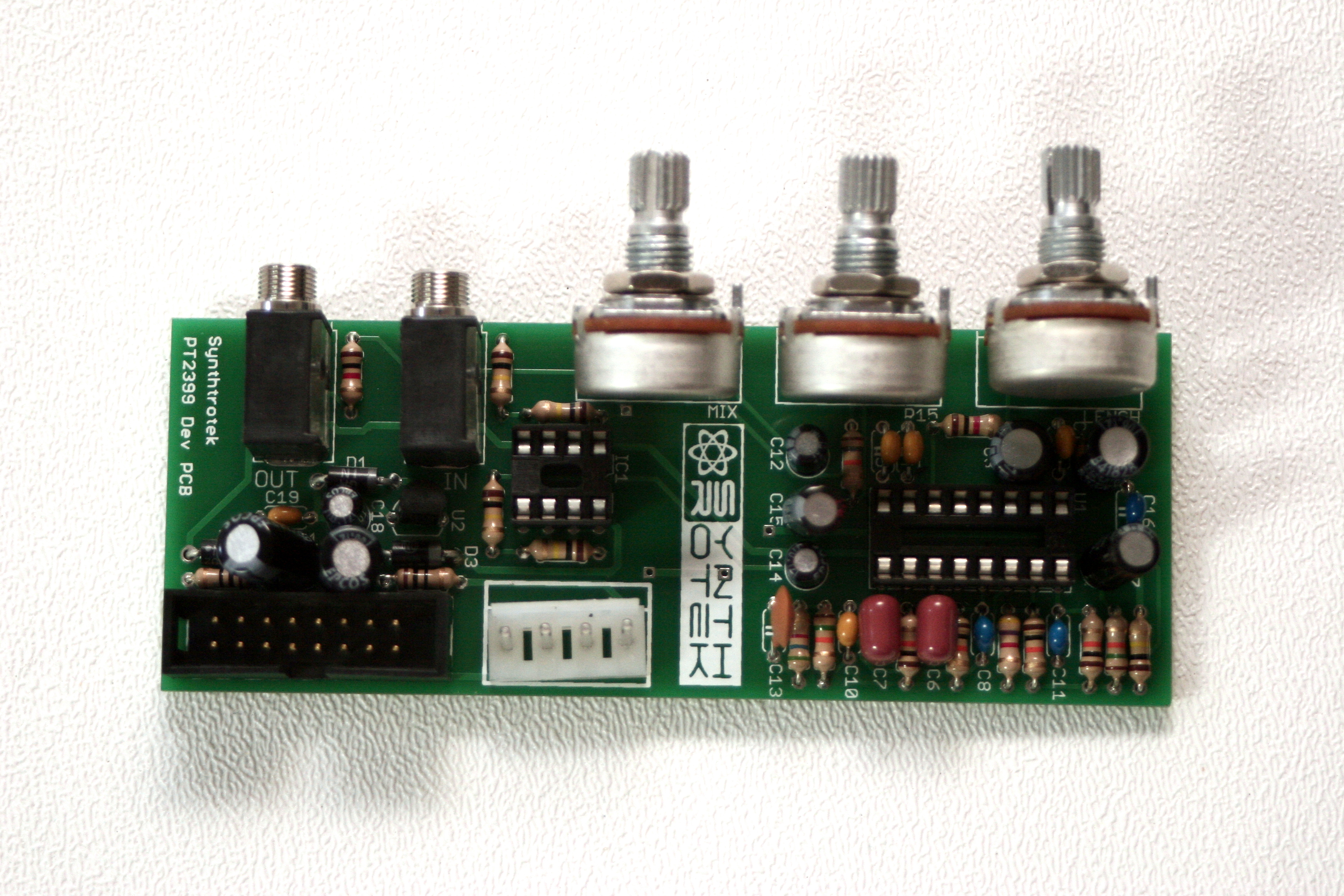
In practice, this should not be lower than 2k2 at startup of the module because otherwise the PT2399 may latch. If you want to get the shortest possible delay time: simply put the pot on zero, and change the 10k resistor by a smaller value. The delay time of the PT2399 is determined by pin 6: a small resistor gives very short delay times (up to chorus effects), higher resistor values make delay times longer, way beyond the official specs!! On the board, there’s a 10k resistor + a 50k pot to adjust the delay time: from 10k to 60k. Time for some mods to make a great module from this board!īefore we implement the mods, we need to make the board eurorack compatible.Ī second thing is: more delay time range! The mono output from the delay circuit is mixed with the stereo input (which we don’t use) by the 2nd NE5532 opamp, and fed to the stereo output (in our case left and right are the same, we just use 1 output). The microphone signal is amplified (1 NE5532 is taking care of that job) and input to the PT2399 delay circuit. The stereo input connection is where you add the stereo karaoke music to the board: we don’t use this. Interesting, because the PT2399 delay chip is mono! First of all, the microphone signals are connected together via a simple resistor, so it’s basically a single input. Here’s a short description of the board connections: there are 2 microphone inputs, a stereo input and a stereo output. In the afternoon, the sun got through the clouds, also on my drawings, so I went on with the karaoke board till the sun was down. Looking at the karaoke board you can spot a PT2399 (a lovely characterful lo-fi delay chip, used in several circuits) and there are also 2 NE5532 opamps: good stuff! Because I could not find the schematics of the karaoke board, I decided to sacrifice a board for reverse engineering on a Sunday morning. The problem was: I had ordered a few boards at once! Of course this made sense: you don’t want endless feedback in a karaoke bar when a singer puts himself in front of a loudspeaker: having input and output in opposite phase is the right way to go!įor my setup, it means I had to change the phase of the delay output by sending it through an attenuverter before feeding it back to the input mixer.Īnd we’re not at the end yet: the delay time range was just covering the sweet range of karaoke.Īs you can guess, my satisfaction level was completely in line with the low price of these karaoke boards! but no, the output and the input were in opposite phase, so the signals were just cancelling out each other. I also splitted the delay output and fed it back to the mixer as well, ready for heavy feedback. So I connected a decaying noise source to a mixer input, and connented the mixer output to the delay module input. So I thought: no problem, I’ll do that with a mixer module. The next thing was the feedback control: it went from 0 to 10, but my preferred setting was definitely over 11: no way to achieve an endless delay! No problem, I thought, a simple voltage divider at the input will do the trick. So I started to use a karaoke delay module in my set-up, but soon noticed that the input level control was not useful between 1.5 and 10, due to clipping distortion and all low end disappearing. So I started building, and yeah, it all worked: I could adjust feedback (rather a dry/wet control), delay time, input level … and from a cheap board you can not expect WOW results anyway! When I saw an article about transforming a cheap Karaoke board into a eurorack delay module, I was excited and ordered a few boards at once.


 0 kommentar(er)
